Airflow Is Not Just CFM: How System-Level Thinking Improves Thermal Performance
For many engineers, fan selection starts and ends with a single number: CFM (cubic feet per minute). Higher CFM feels like a clear win. More air moved must mean better cooling.
In practice, that assumption is one of the most common causes of thermal problems, excess noise, and late-stage redesigns. A fan’s CFM rating describes what it could do in ideal conditions, not what it will do once installed.
Reliable thermal design requires system-level thinking. That means understanding how air behaves inside a real enclosure, how resistance builds, and how a fan actually operates once it encounters that resistance.
Why Free-Air CFM Rarely Matters
A fan’s advertised CFM is measured in free air. This is a test condition with no backpressure, no obstructions, and no enclosure. It represents the absolute maximum airflow the fan can produce under conditions of no load.
The moment that fan is mounted to a chassis, free-air CFM stops being relevant.
Inside a system, air must move through and around restrictive paths: grilles, filters, heat sinks, cable bundles, and PCB assemblies. These obstacles resist airflow and reduce the volume of air the fan can actually change over time. The result is that two fans with the same free-air CFM can perform very differently once installed.
What matters is not the maximum CFM on the datasheet, but the airflow achieved at the fan’s operating point inside your specific system.
Static Pressure and System Impedance
If airflow (CFM) describes how much air moves, static pressure describes how strong the fan can work to move it.
Every physical feature inside an enclosure contributes resistance to airflow. This includes:
PCB spacing and orientation
Component height, placement, and density
Heat sink fin geometry
Filters and protective grilles
Cable routing and internal brackets
The combined resistance of these elements is referred to as system impedance.
As airflow increases, resistance does not increase linearly. It rises much faster, which is why pushing “just a little more air” often requires a disproportionately stronger fan.
This relationship is commonly approximated by the square law:
P = K × Q²
Where:
P is static pressure
Q is airflow (CFM)
K is the system load factor determined by enclosure geometry
The key takeaway is simple: if a fan cannot generate enough static pressure to overcome system impedance, airflow collapses regardless of the fan’s rated CFM. Other unwanted effects like noise and power consumption also increase at a faster rate, sapping overall efficiency.
How the Enclosure and Environment Shape Performance
Fan performance is not fixed. It shifts as the environment around the fan changes. Three contributors consistently have the largest impact.
Dense Layouts
As electronics become smaller and more powerful, internal airflow paths narrow. Tight channels between boards increase air velocity, which sharply raises pressure drop. A fan that performs well in an open layout may struggle once spacing is reduced. Density increases also trap heat, causing component longevity to suffer.
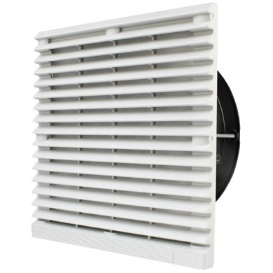
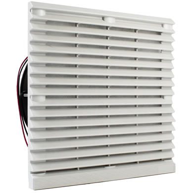
Filters
Filters are often mandatory in medical, industrial, or outdoor systems, but they introduce significant resistance. More importantly, filter resistance increases over time as dust accumulates. A fan that works on day one may operate far from its intended point after months in the field. When regular maintenance is not performed, thermal worst-case scenarios can become common.
Heat Sinks
Heat sinks improve thermal transfer but also block airflow. Dense fin arrays behave like flow restrictors when paired with low-pressure fans. Without sufficient static pressure, air bypasses the fins instead of passing through them. If air pathways are not aligned to maximize flow, efficiency can suffer and increase costs.
Using Fan Curves to Predict Real Performance
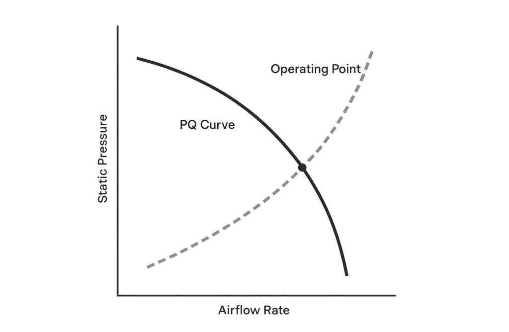
To understand how a fan will behave in your system, you must look beyond a single number and examine the fan’s pressure–flow (PQ) curve.
The PQ curve shows how airflow decreases as static pressure increases. Every fan has a unique curve defined by its blade design and motor characteristics.
To find real operating airflow:
-
Estimate or measure the system impedance curve, which represents how much pressure your enclosure requires at different airflow levels.
-
Overlay the fan’s PQ curve.
-
Identify the intersection point. This is the operating point where the fan will actually run.
If that intersection lies near the low-flow, high-pressure end of the curve, the fan may be spinning fast, generating noise, and delivering very little cooling.
Common Airflow Mistakes Early in Design
Many thermal issues are rooted in mechanical decisions made before airflow is considered.
Treating the Fan as an Afterthought
If an enclosure only allows space for a small fan opening, airflow options become limited regardless of fan choice. Restrictive cutouts force fans to operate at higher pressure and speeds, increasing noise and reducing efficiency.
Poor Inlet and Outlet Balance
A strong exhaust fan cannot compensate for undersized intakes. Restricted inlets increase static pressure and reduce total airflow. Negative pressure inside the enclosure can also result, causing FOD ingress and loss of efficiency. Likewise, without adequate exhaust paths, hot air recirculates inside the enclosure instead of leaving it.
Placing Hot Components in Stagnant Zones
Air does not move evenly through an enclosure. Poor internal layout can create dead zones where heat accumulates. Placing high-power components in these areas leads to localized overheating even when overall airflow seems adequate. Component systems generating the most heat should always be located centrally in the air path to ensure best cooling.
Why Physical Prototyping Still Matters
Computational fluid dynamics tools are valuable, but they rely on assumptions that may not capture every real-world variable. Physical testing and validation remains essential.
Prototyping with real thermal loads allows engineers to:
-
Identify unexpected hotspots
-
Measure actual acoustic behavior
-
Validate airflow direction and leakage paths
-
Measure temperature differences to calculate effective CFM and cooling performance
-
Test degraded conditions such as clogged filters or fan failure
These insights often reveal issues that are invisible in simulation.
Designing for Reliability, Not Just Compliance
Selecting fans based on operating point and static pressure rather than maximum CFM reduces redesign risk and improves long-term reliability. Fans operating in the efficient region of their curve generate less noise, experience less mechanical stress, and maintain airflow as system resistance changes over time.
More importantly, proper airflow control keeps components within their thermal limits under real operating conditions. That means fewer capacitor failures, less processor throttling, and systems that perform as intended in the field, not just on the bench.